Differentiate Between Continuous Co2 Injection and Water Alternating Gas
Abstract
The Water Alternating Gas (WAG) process is a cyclic process of injecting alternating water followed by gas. The main purpose of WAG injection is to improve both macroscopic and microscopic sweep efficiency, maintaining nearly initial high pressure, slow down the gas breakthrough and reduced oil viscosity. WAG injection also decreases the residual oil saturation resulted from the flow of three phases and effects associated with relative permeability hysteresis. The study area is in the Cornea Field located in Browse Basin, Western Australia. This study is conducted because there is no investigation on WAG injection feasibility in this field. In this study, two-phase bounding imbibition and drainage relative permeability model (Stone 1 and Stone 2) along with two-phase hysteresis model (Land, Carlson or Killough) were used. From the result, Carlson two-phase hysteresis model with Stone 1 correlation shows more oil was recovered. Therefore, it is a feasible model to be used compared with other models. From sensitivity analysis, it shows that highest oil was recovered at WAG ratio 1:1. Since it is a miscible reservoir, 1:1 ratio is more efficient and it is insensitive to trapping. Also, oil production increased with the shortest WAG cycle time at 180 days due to minimum miscibility pressure reached. In addition, it is best to inject water as the first phase to be injected into the reservoir compared to CO\(_{2}\) because water has high mobility ratio while CO\(_{2}\) can result in early breakthrough in the reservoir.
Introduction
The Water Alternating Gas (WAG) process is a cyclic process of injecting alternating gas followed by water and repeating this process for number of cycles. The main purpose of WAG injection is to improve oil production recovery, which help to improve both macroscopic and microscopic sweep efficiency, maintaining reservoir pressure, slow down the gas breakthrough, viscosity reduction caused by the gas dissolution in oil, fluid composition variation and decrease the residual oil saturation resulted from the flow of three phases and effects associated with relative permeability hysteresis (Hussien 2013).WAG injection involves drainage (D) and imbibition (I) taking place simultaneously or in cyclic alternation in the reservoir (Fabusuyi 2013).The WAG method also provides the mobility control which improve the gas project life and oil recovery. Carbon dioxide gas is usually use for miscible (Belazreg and Mahmood 2020) displacement due to less pressure and further improve sweep efficiency. The gas injection has higher microscopic displacement efficiency (Zekri et al. 2015) than the water injection efficiency due to its low interfacial tension between oil and gas phase (Mohammad and Mahmoud 2018).
WAG injection is also use to contact attic oil which is not contacted during water injection alone. In high permeable sandstone reservoir, gravity segregation is common; therefore, gas will tend to move to the top of reservoir and dense water will tend to migrate to the bottom of the reservoir. Therefore, by using WAG injection, attic oil in the upper part of the reservoir may be contacted by the injected gas and water flood will push the miscible slug. This will increase the microscopic efficiency because the unswept reservoir area will be smaller. Less residual oil will remain in the reservoir and thus improved the oil recovery. See Fig. 1 below for the gravity effect during gas, water and WAG injection illustrated in Mohammad and Mahmoud (2018). Supplies of biodiesel appear to have outstripped demand in many countries but not a realistic solution of today's world demand (Hemisphere 2008).
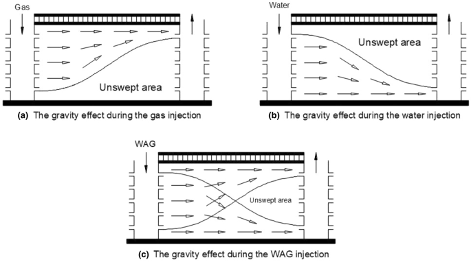
The gravity effect during gas, water and WAG injection (Mohammad and Mahmoud 2018)
WAG injection is widely used worldwide because it has been proven that WAG injection is a better method than gas injection and water injection. In terms of economic evaluation, gas injection is an expensive operation; therefore, WAG is a better method to be implemented because the amount of gas injection in WAG is less than amount of gas injected in continuous gas injection. WAG has been tested and used in a deep reservoir, onshore, offshore and in different stratigraphy. Most studied WAG injection was on miscible and immiscible WAG injection (Mohammad and Mahmoud 2018). However, the aim of this study is to focus on the miscible WAG injection which is related to previous study by Abdullah and Hasan (2020) where the results need to be further improve using WAG injection after CO2 injection. The study area is in the Cornea Field located in Browse Basin, Western Australia. It is a simple trap structure which is elongated and formed by unfaulted drape anticline over eroded high basement (Ingram et al. 2000). This study is conducted because there is no investigation previously in the Cornea Field on the WAG injection after CO\(_{2}\) injection (Fig. 2).
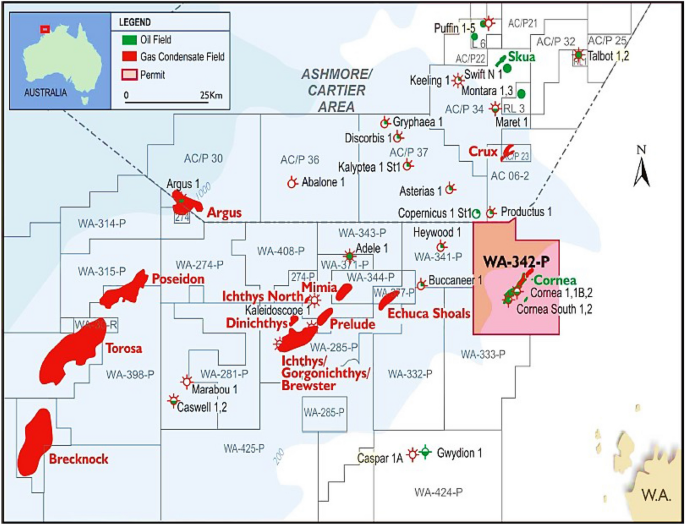
Cornea Field in Browse Basin, Western Australia (box)
Optimization scenario of natural production, water flooding, gas injection, individual and simultaneous WAG parameters on recovery factor was studied by Sadeghnejad et al. (2019) on Iranian formation. A simulated annealing optimizer was coupled with reservoir simulator to investigate the different production-injection scenarios. Kinetic model for a big model like this is a complex phenomena (Bera et al. 2013). Iranian formation data were used to develop a model. Operation constraint such as production mode change, closing perforations above a maximum water-cut or GOR limit was analyzed. From the result, the operational constraints could considerably change the production characteristics of a flooding scenario by adjusting the production mechanism, for instance, from solution-gas-drive to secondary gas cap drive. Therefore, these production restrictions could modify the optimal scenario and should always be analyzed. The recovery factor of the WAG scenario at 46% was higher compared with the optimized natural production at 28.9%, waterflooding at 35.5% and gas injection at 39.1%. The ultimate recovery factor of the individual WAG parameter showed less recovery at 43.4% than the simultaneous optimization of all parameters at 46%. Therefore, all parameters should be optimized together during simulation. The WAG ratio was remained constant at 1:1 during the simulation (Sadeghnejad et al. 2019; Karaei et al. 2014; Wern 2014; Han 2015).
An investigation by Saikou (2013) to improve oil recovery by using WAG injection as an enhanced recovery technique at laboratory scale was implemented in Wallace sandstone. Initially, water and gas injection was performed on this reservoir core plugs named W25, W16 and W26 followed by WAG injection. Core flooding was conducted using Benchtop Relative Permeameter (BRP). Both water and gas injection achieves good recoveries of oil with a minimum recovery of 26.13% OOIP and maximum recovery of 61.24% OOIP. An additional oil recovery was achieved in W25, W16 and W26 of 9.02%, 19.05% and 21.04% OOIP after applying WAG injection. WAG injection has higher oil recovery of 12% when WAG injection was preceded by water flooding then when WAG injection was preceded by gas injection. This was due to water that follows the gas injection during WAG was able to control the high mobility of gas phase and stabilized the displacement front (Saikou 2013; Jafari et al. 2008; Bhatia et al. 2014).
Another recovery potential using water injection and carbon dioxide injection coupled with WAG injection, based on injection well location, was investigated in the Uganda oil filed by Marembo and Asasira (2019), where only appraisal and no production observed. This study used standard correlation equation, filed analogs and compared existing literature to foresee the potential oil recovery of Albertine reservoir (Marembo and Asasira 2019). Field analogs are suitable for estimating oil recovery factor for an oil reservoir in appraisal stage. The oil recovery factor field analogs for primary production were between 8 and 15%, while oil recovery factor calculated from empirical correlation equations was between 18.2 and 62%. The simulated primary production oil recovery was from 9.81% (injection was at a distance of 60ft from producer) to 36.85% (injection was at a distance of 800ft from producer). This indicated the effect of injection well location with respect to the production well on oil recovery factor. Both secondary water and carbon dioxide injections yield good recovery factor of 31.6% OOIP and 62.3% OOIP, respectively. Additional oil was also discovered using WAG injection. When WAG injection was preceded by waterflooding, the oil recovery factor was 12% OOIP higher than when WAG preceded by carbon dioxide gas.
On the other hand, Suphattra (2010) also implemented WAG injection method and analyzed the operation condition to optimize oil production in Phitsanulok Basin oil field. Eclipse 300 program was used to implement the suitable operation method to boost the oil recovery in this filed. Few conceptual production and injection scenarios were applied, which were no injection (natural flow) and WAG injection at 1st year, 2nd year, 4th year and 8th year after natural flow production. The economic analysis and sensitivity analysis in oil price were also taken into account. From the reservoir simulation, it shows that the WAG method can improve oil recovery efficiency when compared with natural flow under same condition. Injection at 2nd year after the natural flow was the best case operation and development due to higher recovery factor and more economical value when compared with other. From the result, it shows that the oil recovery from primary production is 10.54% of OOIP, while WAG achieves the highest recovery up to 71.05%. However, in terms of economic evaluation, WAG method was not preferable due to its high cost facilities and it was not economical.
In Jacksonburg–Stringtown mature oil fields, northwest Virginia, huge amount of remaining oil in place has not been recovery in primary and secondary production. The OOIP in this area has 88 MMBBL, and only around 22 MMBBL was produced. This means that more than 55 MMBBL of residual left behind in this reservoir and 5 MMBBL to 11 MMBBL might be recovered from CO2-EOR recovery method. This field provided an opportunity to enhance oil recovery and isolate large amount of injected CO2 into underground reservoir. Study by Zhong et al. (2019) established and validated the workflow for CO2 storage and CO2-WAG on the Jacksonburg–Stringtown oil field. Small-scale compositional numerical modeling using compositional CMG GEM software was used in this study. From the result, it shows the amount of CO2 and water cycling affected both CO2-WAG performance and the amount of CO2 stored within the reservoir. In addition, WAG ratio and injection rate had a significant impact on oil recovery factor. The recovery factor ranges from 27 to 28%. From the reservoir simulation, it was seen that WAG process increased the sweep coefficient and decreased mobility ratio between water and oil phases and improves the total oil recovery factor.
Experimental immiscible WAG flood was established by Srivastava and Laxminarayan (2012) to improve the microscopic displacement efficiency (Report 2010) with water flooding and gas injection. Laboratory displacement studies were conducted on the GS-5C sand from matured light oil field in Gandhar, India. From the core sample, it was observed that the WAG injection gave better sweep efficiency, mobility control of water and gas phases and improved displacement efficiency. It can be seen that the number of WAG cycles affects the oil recovery factor. An incremental displacement efficiency at single cycle was 12.75% HCPV, while five cycle was 19.3% of HCPV. The CO2 injection in WAG process had a better displacement efficiency about 40% HCPV when compared with water flood.
Another coreflood experiment by Madhav (2003) was conducted with the objective to evaluate miscible and immiscible WAG in short and long cores from Berea, Ohio, as a function of gas-oil miscibility and brine composition. The oil recoveries from WAG and continuous gas injection (CGI) were compared. Miscible injection was conducted at 2500 psi and immiscible injection at 500 psi. The procedure of coreflooding was conducted in steps with brine saturation, absolute permeability determination, flooding with oil (drainage) to initial oil saturation, end-point oil permeability determination, flooding with brine (imbibition) to residual oil saturation, end-point water permeability determination and finally, tertiary gas injection to recover the waterflood residual oil. Two different brines were used: 5% NACl solution and actual reservoir brine to examine the effects of rock fluid interactions. n-Decane was used as the oleic phase and pure carbon dioxide as the injected gas. Ten corefloods with eight 1ft and two with 6ft long were experimented. From the experiment, it shows that the recovery for both CGI and WAG immiscible flood yielded 23%, while recovery for WAG miscible flood was at 84.5% and CGI was at 93.7%. This shows that miscible flooding was better than immiscible flooding (Madhav 2003; Shahverdi et al. 2018).
Experimental study by Vahid et al. (2017) aimed at evaluating the performance of the miscible WAG flooding and WAG ratio on oil recovery factor in Sarvak formation, SW Iran. Slim-tube apparatus was used to obtain the minimum miscibility pressure (MMP) at constant reservoir temperature. Seven core floodings were performed using sandstone core sample collected from Sarvak formation. Water flooding, miscible continuous CO2 flooding and miscible WAG flooding were experimented. In miscible WAG, slug sizes of 0.15, 0.25 and 0.5 pore volume and WAG ratio of 1:1, 2:1 and 1:2 were used to examine the effect on oil recovery factor. From the result, it shows that miscible WAG has the highest oil recovery factor at 84.3% when compared with water flooding at 37.7% and miscible CO2 flooding at 61.5%. Thus, miscible WAG flooding was capable of mobilizing heavy oil and optimizing oil recovery factor. From the experiment, using a smaller slug size for miscible WAG flooding gave the highest oil recovery factor. The optimum WAG ratio for miscible WAG flooding was at 2:1. In the miscible WAG flooding, more that 50% of heavy oil was produced in the first two cycles and had less CO2 consumption than miscible CO2 flooding (Vahid et al. 2017; Oladepo et al. 1920; Salleh 2014).
Contrarily, Tianjie (2016) developed an effective workflow to evaluate strategies for completing Cardium field, Canada, horizontal wells and their suitability for conducting CO2 injection for EOR. Different WAG injection schemes were also conducted and compared with CO2 injection which included constant WAG, SWAG and hybrid WAG injection. The effects of different WAG parameters were also considered. The compositional simulator was used to simulate the CO2 injection, and the equation of state (EOS)-based fluid model was established and tuned to characterized reservoir fluid. The tuned fluid was matched with experimental PVT behavior of Cardium fluids. The fuzzy analytic hierarchy process (F-AHP) as a powerful multiple criteria decision-making technique was used and lastly, design of experiment (DOE) as a statistical method for conducting sensitivity analysis and assisted reservoir simulation and F-AHP. Two parameters were defined to evaluate the strategies for completing horizontal wells included reservoir quality and well completion quality groups. From the sensitivity analysis, the least significant factor in reservoir quality group was reservoir permeability, the fluid type, remaining oil saturation and reservoir depth or pressure. It has been validated using reservoir simulation and it was efficient and suitable to be used for other fields. For WAG injection, it shows that oil recovery factor increased with increased in WAG ratio but not WAG length cycle. The optimum WAG ratio was 2:1, and WAG cycle length was for 18 months (Tianjie 2016; Aghdam and Ghorashi 2017; Hutthapong and Kreangkrai 2018; Kavanrudi et al. 2017; Maliheh et al 2012).
Lastly, WAG injection was also studied by Fabusuyi (2013) by constructing an upscaled reservoir, oil composition model and implementing WAG injection scheme, to evaluate the reservoir performance and developed production strategies. The reservoir data from Brazilian pre-salt were used modeled CERENA-1 static model. Due to insufficient of real data, fluid composition was obtained from sample in the Schlumberger's Petrel fluids library and PVT behavior to match the estimated bubble point of the oil and modeled using tuned equation of state Schlumberger's PVTi package. The dynamic flow simulation was run in Schlumberger's Eclipse 300 and tNavigator by Rock Flow Dynamics and the optimization process was done using Raven by Epistemy. WAG ratio and injection rate were tested in this research. Initially, random WAG ratio was applied to each of the injection rate. However, it can be seen that the injection rate changes with changes in WAG ratio. To obtain more valid result, 1:2, 2:3 and 1:5 WAG ratios were tested to each of the injection rate. From the result, it shows that the optimal WAG ratio was 2:3 and the ideal injection rate of water was at about 40,000 sm3/day, while the gas would be at about 60,000 sm3/day. Oil production of about 10M sm3 was recovered from 15M sm3 OOIP at this injection rate. The recovery factor is about 68%. This study was based on macro-study effect; to further improve the recovery factor, future study of the micro-study injection scheme and possibility of adding surfactant were recommended (Jonas 2015).
From the literature review, it shows that WAG injection was a better technique compared to CO2 injection. Therefore, the aim of this study is to improve the oil production and recovery factor using WAG injection. The objectives of this research are:
- 1.
To implement WAG injection simulation into the Cornea Field
- 2.
To determine feasible relative permeability hysteresis model
- 3.
To conduct sensitivity analysis on operational parameters to see the effects on WAG injection
- 4.
To evaluate the effect of WAG injection on oil production recovery in the Cornea Field for 20 years
Methodology
Data were mostly collected from Geoscience Australia, and some were from Occam Technology Company. The model was constructed using the PETREL software by importing data collected. Fluid composition was obtained from PVTi program and imported into ECLIPSE software. The WAG injection was establish using data coding.
In WAG injections simulation, relative permeability data and hysteresis effects need to be taken into account for valid WAG simulation. The first approach is to use two-phase bounding imbibition and drainage relative permeabilities (Stone 1 and Stone 2) along with two-phase hysteresis model (Land, Carlson or Killough) to simulate hysteresis in WAG injection. EHYSTR Keyword was used in ECLIPSE data for WAG two-phase hysteresis model. Another approach is using three-phase hysteresis model which is also WAG-hysteresis model (Larsen and Skauge) along with Stone 1/Stone 2 correlation. WAGHYSTR Keyword was used in ECLIPSE data for WAG three-phase hysteresis model. These correlations and models are developed based on high oil/gas interfacial tension and water wet system (Fatemi 2015; Serdar 2008; Ole 2012; Arne and Jan 2003).
-
Relative permeability model:
-
Stone 1(1970)
Stone 1 uses two set of two-phase data to predict the relative permeability of the intermediate wet phase in three-phase system. It provides interpolated data for three-phase flow that are consistent and continuous functions of phase saturation (Shahverdi 2012). The original Stone's first model was modified by Aziz and Settari in 1979 for end-point relative permeability as below:
$$\begin{aligned} K_{\mathrm{ro}}=\frac{S_\mathrm{o}^**K_{\mathrm{row}}{*K}_{\mathrm{rog}}}{K_{\mathrm{rocw}}\left( 1-S_{\mathrm{w}}^*\right) \left( 1-S_{\mathrm{g}}^*\right) } \end{aligned}$$
\(S_\mathrm{o}^*\), \(S_{\mathrm{g}}^*\) and \(S_{\mathrm{w}}^*\) are calculated as below when \(S_\mathrm{o}>S_{\mathrm{om}}\) and \(S_{\mathrm{w}}>S_{\mathrm{wc}}\)
$$\begin{aligned} S_\mathrm{o}^*= \,& {} \frac{S_\mathrm{o}-S_{\mathrm{om}}}{1-S_{\mathrm{wc}}-S_{\mathrm{om}}} \\ S_{\mathrm{w}}^*= & {} \frac{S_{\mathrm{w}}-S_{\mathrm{wc}}}{1-S_{\mathrm{wc}}-S_{\mathrm{om}}} \\ S_{\mathrm{g}}^*= & {} \frac{S_{\mathrm{g}}}{1-S_{\mathrm{wc}}-S_{\mathrm{om}}} \end{aligned}$$
-
Stone 2 (1973) Modified Stone 2 (1973) on the other hand, integrated gas and water relative permeability in calculation of three phase of the oil in mixed wet in order to get better agreement with experiment data (Shahverdi 2012).
$$\begin{aligned} K_{\mathrm{ro}}= & {} K_{\mathrm{rocw}}\left( \left( \frac{K_\mathrm{rw}}{K_{\mathrm{rocw}}}+K_\mathrm{rw}\right) \right. \\&\left. \left( \frac{K_{\mathrm{rg}}}{K_{\mathrm{rocw}}}+K_{\mathrm{rg}}\right) -K_\mathrm{rw}-K_{\mathrm{rg}}\right] \end{aligned}$$
\({K}_\mathrm{rw}\) and \(K_{\mathrm{rg}}\) are read from two-phase oil/water and oil/gas system relative permeabilities
-
Baker (1988) Baker proposed a simple three-phase relative permeability oil, water and gas based on saturation-weighted interpolation between two-phase relative permeability data in which three phase of each phase is assumed to be function of two saturation (Shahverdi 2012; Raz 2017; Lin et al. 2014).
$$\begin{aligned} K_{\mathrm{ro}}=\frac{S_{\mathrm{g}}K_{\mathrm{rog}}+\left( S_{\mathrm{w}}-S_{\mathrm{wc}}\right) K_{\mathrm{row}}}{S_{\mathrm{g}}+S_{\mathrm{w}}-S_{\mathrm{wc}}} \end{aligned}$$
-
Two-phase hysteresis model:
-
Land trapping model Land proposed a relationship for calculating relative permeability for two- and three-phase flow for non-wetting phase in the decreasing saturation direction. This relationship honored the trapping coefficient of the non-wetting phase as the saturation starts to deplete (imbibition) and was dependent on the saturation maximum achieved during increasing saturation direction (drainage) (Tasleem 2010; Larsen and Skauge 1995).
$$\begin{aligned} S_{\mathrm{gt}}=\frac{S_{\mathrm{gi}}}{1+CS_{\mathrm{gi}}} \end{aligned}$$
Land coefficient, C is computed as below:
$$\begin{aligned} C=\frac{1}{S_{\mathrm{gt,max}}}-\frac{1}{S_\mathrm{gi,max}} \end{aligned}$$
-
Killough (1976) and Carlson (1981) Killough and Carlson further developed the land saturation history-dependent model by including the hysteresis effects in non-wetting phase. The Killough model hysteresis assumption on non-wetting phase hysteresis is the same as Carlson model. The only difference between these two models is that the trapped non-wetting phase saturation would be predicted using Land's model along with different formulation for scanning curve. In Carlson model, the scanning curve is assumed to be parallel to the imbibition curve. It obtained by shifting the bounding imbibition curve horizontally until it intersects the drainage curve (Spiteri and Juanes 2006).
Carlson trapped gas saturation:
$$\begin{aligned} S_{\mathrm{gt}}=S_{\mathrm{gt}}^{\mathrm{max}}-{\triangle S}_{\mathrm{gi}} \end{aligned}$$
Killough non-wetting phase relative permeability along the scanning curve is computed as:
$$\begin{aligned} K_{\mathrm{rg}}^{\mathrm{imb}}\left( S_{\mathrm{g}}\right) =\frac{K_{{\mathrm{rg}}\left( {\mathrm{o}}\right) }^{\mathrm{imb}}(S_{\mathrm{g,norm}})K_{{\mathrm{rg}}\left( {\mathrm{o}}\right) }^{\mathrm{dr}}(S_{\mathrm{g,hy}})}{K_{{\mathrm{rg}}\left( {\mathrm{o}}\right) }^{\mathrm{dr}}(S_\mathrm{g,max})} \end{aligned}$$
where \(S_{\mathrm{g,norm}}=S_{\mathrm{gt,max}}+\frac{(S_{\mathrm{g}}-S_{\mathrm{gt}})(S_\mathrm{g,max}-S_{\mathrm{gt,max}})}{S_{\mathrm{g,hy}}-S_{\mathrm{gt}}}\)
-
Three-phase hysteresis model
-
Larsen and Skauge (1998)
Larsen and Skauge model is use to simulate the WAG hysteresis in combination with the standard two-phase hysteresis models (Spiteri and Juanes 2006).
Non-wetting relative permeability on the drainage to imbibition scanning curve and vice versa:
$$\begin{aligned} K_{\mathrm{rg}}^{\mathrm{imb}}\left( S_{\mathrm{g}}\right) =K_{\mathrm{rg}}^{\mathrm{dr}}(S_{\mathrm{gf}}) \end{aligned}$$
where free gas saturation using Land's equation:
$$\begin{aligned} S_{\mathrm{gf}}= & {} S_{\mathrm{gc}}+\frac{1}{2}\left( {(S}_{\mathrm{g}}-S_{\mathrm{gt}})\right. \\&\left. +\sqrt{{{(S}_{\mathrm{g}}-S_{\mathrm{gt}})}^{2}+\frac{4}{C}{(S}_{\mathrm{g}}-S_{\mathrm{gt}})}\;\right] \end{aligned}$$
and non-wetting phase using land trapping model:
$$\begin{aligned} S_{\mathrm{gt}}=S_{\mathrm{gc}}+\frac{S_{\mathrm{g,hy}}-S_{\mathrm{gc}}}{1+C(S_{\mathrm{g,hy}}-S_{\mathrm{gc}})} \end{aligned}$$
Secondary drainage relative permeability curve:
$$\begin{aligned} K_{\mathrm{rg}}^{\mathrm{dr}}\left( S_{\mathrm{g}},S_{\mathrm{g}}^\mathrm{start},\;S_{\mathrm{w}}^\mathrm{start}\right)= & {} K_{\mathrm{rg}}^{\mathrm{imb}}\left( S_{\mathrm{g}}^\mathrm{start}\right) +\left( K_{{\mathrm{rg}}\left( {\mathrm{o}}\right) }^{\mathrm{dr}}\left( S_{\mathrm{g}}\right) \right. \\&\left. -K_{{\mathrm{rg}}\left( {\mathrm{o}}\right) }^{\mathrm{dr}}\left( S_{\mathrm{g}}^\mathrm{start}\right) \right) {\left( \frac{S_{\mathrm{wc}}}{S_{\mathrm{w}}^\mathrm{start}}\right) }^\propto \end{aligned}$$
Results and discussion
Different interpolation model and hysteresis model were used to determine the feasibility of the model to be implemented on this reservoir. See Table 1 for recovered oil production using different relative permeability models and hysteresis models.
From the results, it shows that Carlson two-phase hysteresis model with Stone 1 interpolation model was more feasible and recovered more oil production. In addition, two-phase hysteresis model has been the standard in most reservoir simulation. Three-phase WAG hysteresis model was not feasible for this reservoir since this is a miscible reservoir. In addition, three-phase hysteresis simulation was time-consuming. From Table 1, it can be seen that case 5 has the highest oil production; therefore, it was validated as a feasible model and suitable to be used for sensitivity analysis to see the effect of the WAG parameters on oil production.
Three WAG factors were investigated for the sensitivity analysis of the effect of below parameter on oil recovery:
- 1.
WAG ratio Case 5 was used to investigate the effect of WAG ratio by running 4 cases: 1:1, 1:2, 2:1 and 3:1. From Fig. 3, it shows that 1:1 produced the highest oil production where equal water and gas injected for maximum recovery. Since this is a miscible reservoir, equal WAG ratio is more efficient and insensitive to trapping. The ratios other than 1:1 which are 1:2, 2:1 and 3:1 show lower oil recovery. Please refer Fig. 4 for focused field oil total production from year 2036 to 2038 and Fig. 5 for field water total production from 2019 to 2038.
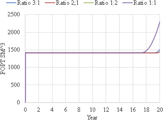
FOPT versus year for WAG ratio 1:1, 1:2, 2:1 and 3:1
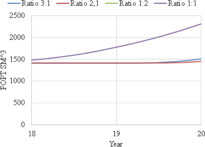
Focused FOPT versus year for WAG ratio 1:1, 1:2, 2:1 and 3:1
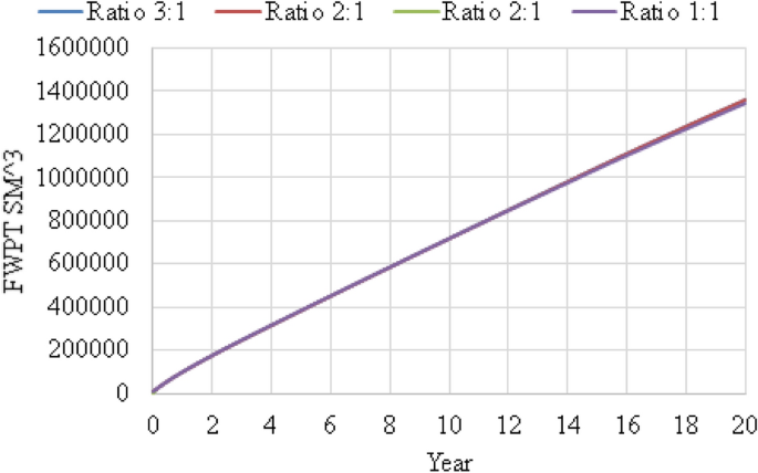
FWPT versus year for WAG ratio 1:1, 1:2, 2:1 and 3:1
WAG cycle time
Effect of WAG cycle time was investigated by running 5 cases: 180 days, 270 days, 360 days, 450 days and 540 days. From Fig. 6, it shows that the oil production was constant then increased with decreased in WAG cycle time from 2035 to 2038. It can be seen that the favorable cycle time is 180 days. This is because it is best to inject \(CO_{{}^{2}}\)and water in the shortest time with the lowest number of cycle where miscibility of the reservoir reached where pressure is above minimum miscibility pressure. Please refer Fig. 7 for focused field oil total production from year 2036 to 2038 and Fig. 8 for field water total production from 2019 to 2038.
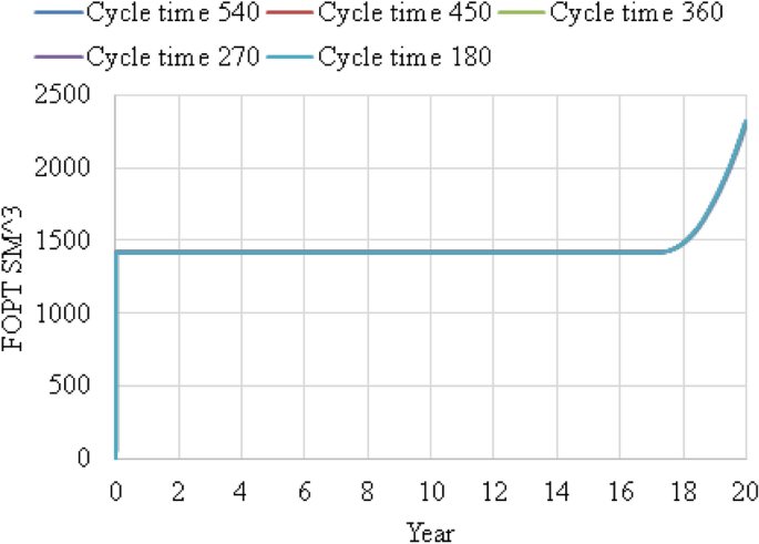
FOPT versus year for WAG cycle time 180 days, 270 days, 360 days, 450 days and 540 days
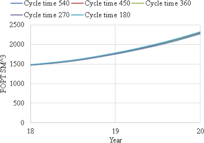
FocusedFOPT versus year from 2036 to 2038 for WAG cycle time 180 days, 270 days, 360 days, 450 days and 540 days
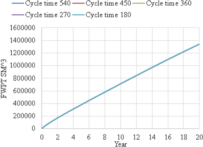
FWPT versus year for WAG cycle time 180 days, 270 days, 360 days, 450 days and 540 days
First phase injected in WAG injection
From Fig. 6, water was the first phase injected into the reservoir then followed with \(CO_{{}^{2}}\) injection. It shows that the oil production increased with shortest cycle time in 180 days. In this case, \(CO_{{}^{2}}\) was the first phase injected into the reservoir then followed by water injection. Five cases were also tested: 180 days, 270 days, 360 days, 450 days and 540 days. From Fig. 9, it shows contradicting result with Fig. 6 even though they showed same trend. From Fig. 9, it shows that the oil production increased with increase in cycle time at 540 days. Since it shows that oil production increased with increase in cycle time, therefore, it proves that water was the best phase to be injected first rather than \(CO_{{}^{2}}\). This is because oil saturation is high at the early stage of the production; therefore, it is better to inject water which has high mobility and produced more oil in an early stage. \(CO_{{}^{2}}\) are not preferable to be injected first due to its low mobility and can result in early breakthrough and viscous fingering. Please refer Fig. 10 for focused field oil total production from year 2036 to 2038 and Fig. 11 for field water total production from 2019 to 2038.
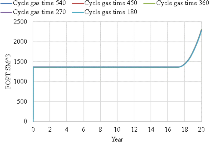
FOPT versus year for WAG cycle time 180 days, 270 days, 360 days, 450 days and 540 days with gas injected as first phase
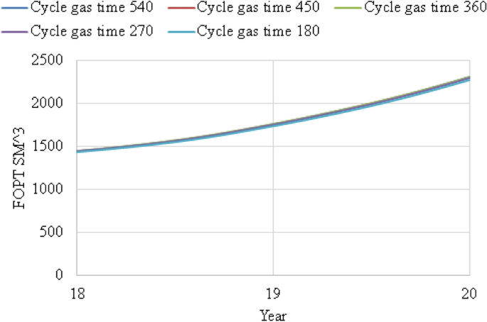
Focused FOPT versus year from 2036 to 2038 WAG cycle time 180 days, 270 days, 360 days, 450 days and 540 days with gas injected as first phase
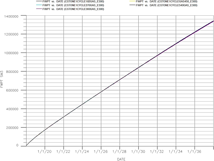
FWPT VS year WAG cycle time 180 days, 270 days, 360 days, 450 days and 540 days with gas injected as first phase
Conclusion
Few findings were determined from this study (Table 2):
- 1.
Relative permeability model and hysteresis model need to be considered to have a feasible WAG model. The Carlson two-phase hysteresis model with Stone 1 correlation was more feasible, and more oil was recovered compared with other scenarios.
- 2.
The WAG ratio at 1:1 produced the highest oil recovery since it is a miscible oil reservoir. It is also more efficient WAG ratio and insensitive to trapping.
- 3.
Oil production increased with the shortest WAG cycle time at 180 days due to minimum miscibility pressure reached.
- 4.
It is best to inject water as the first phase to be injected into the reservoir compared to \(CO_{{}^{2}}\) because water has high mobility ration while v can result in early breakthrough.
In conclusion, it shows that WAG injection is a better method when compared with flooding alone. The study can be further improved by considering implementing WAG with nitrogen gas to foresee its effect on oil production recovery.
Abbreviations
- OOIP:
-
Original oil in place
- MMBBL:
-
Million Barrel
- HCPV:
-
Hydrocarbon pore volume
- FOPT:
-
Field oil production total
- FWPT:
-
Field water production total
- \(K_{\mathrm{ro}}\) :
-
Oil relative permeability
- \(K_{\mathrm{rog}}\) :
-
Gas relative permeability
- \(K_{\mathrm{row}}\) :
-
Water relative permeability
- \(K_{\mathrm{rocw}}\) :
-
Relative permeability to oil at connate water
- \(S_{\mathrm{o}}^*\) :
-
Normalized oil saturation
- \(S_{\mathrm{g}}^*\) :
-
Normalized gas saturation
- \(S_{\mathrm{w}}^*\) :
-
Normalized water saturation
- \(S_{\mathrm{wc}}\) :
-
Saturation at connect water
- \(S_{\mathrm{om}}\) :
-
Minimum residual oil saturation
- \(S_{\mathrm{gt}}\) :
-
Trapped gas saturation
- \(S_{\mathrm{gi}}\) :
-
Initial gas saturation
- C :
-
Land coefficient parameter
- \(S_{\mathrm{gt,max}}\) :
-
Maximum trapped gas saturation
- \(S_{\mathrm{gi,max} }\) :
-
Maximum initial gas saturation
- \(K_{\mathrm{rg}}^{\mathrm{imb}}\) :
-
Imbibition gas relative permeability
- \(K_{\mathrm{rg}}^{\mathrm{dr}}\) :
-
Drainage gas relative permeability
- \(S_{\mathrm{g,norm}}\) :
-
Normalized gas saturation
- \(S_{\mathrm{g,hy}}\) :
-
Gas saturation after flow reversal
- \(S_{\mathrm{gf}}\) :
-
Flowing gas saturation
- \(S_{\mathrm{gc}}\) :
-
Critical gas saturation
- \(\propto\) :
-
Secondary drainage reduction coefficient
References
-
Abdullah N, Hasan N (2020) The study of the effects of miscible CO2 injection on production recovery in Cornea Field. Western Australia
-
Aghdam KA, Ghorashi SS (2017) Critical parameters affecting Water Alternating Gas (WAG) injection in an Iranian fractured reservoir. J Pet Sci Technol 7(3):3–14
-
Arne S, Jan AS (2003) Review of wag field experience. In: 1st international conference and exhibition modern challenges in oil recovery
-
Belazreg L, Mahmood SM (2020) Water alternating gas incremental recovery factor prediction and WAG pilot lessons learned. J Pet Explor Prod Technol 10:249–269. https://doi.org/10.1007/s13202-019-0694-x
-
Bera A, Kumar T, Ojha K, Mandal A (2013) Adsorption of surfactants on sand surface in enhanced oil recovery: isotherms, kinetics and thermodynamic studies. Appl Surf Sci 284:87–99
-
Bhatia J, Srivastava JP, Sharma A, Sangwai JS (2014) Production performance of water alternate gas injection techniques for enhanced oil recovery: effect of WAG ratio, number of WAG cycles and the type of injection gas. Int J Oil Gas Coal Technol 7(2):132. https://doi.org/10.1504/ijogct.2014.059323
-
Fabusuyi OJ (2013) Composition fluid flow simulation with water alternating gas injection optimization on the upscaled synthetic reservoir CERENA-1. TECNICO LISBOA, Lisboa, p 91
-
Fatemi SM (2015) Multiphase flow and hysteresis phenomena in oil recovery by water alternating gas (WAG) injection. Thesis, Petroleum Engineering, Heriot-Watt University
-
Han L (2015) Optimum water alternating gas (CO2-WAG) injection in Bakken formation. Thesis, Petroleum Systems Engineering University of Regina
-
Hemisphere (2008) Asia's biodiesel producers find life hard. Oil Energy Trends 33(1):13
-
Hussien MYA (2013) Simulation study on IWAG assisted by low salinity water injection for light oil reservoirs. Thesis, Universiti Teknologi Petronas, Malaysia
-
Hutthapong Y, Kreangkrai M (2018) CO2 geological storage coupled with water. Ital Assoc Chem Eng 63:217–222
-
Ingram GM, Eaton S, Regtien JMM (2000) Cornea case study: lesson learned. APPEA J 40(1):56–65
-
Jafari M, Badakhshan A, Taghikhani V, Rashtchian D, Ghotbi C, Sajjadian VA (2008) Experimental study and simulation of different EOR techniques in a non-fractured carbonate core from an Iranian offshore oil reservoir. Iran J Chem Chem Eng 2:27
-
Larsen JA, Skauge A (1995) Comparing hysteresis models for relative permeability in WAG studies. In: SCA conference 1995. Norsk Hydro Research Centre/University of Bergen, Norway
-
Jonas S (2015) Water alternating gas in stratified reservoirs: a sensitivity study of WAG parameters. Thesis, Department of Petroleum Engineering and Applied Geophysics, Norwegian University of Science and Technology
-
Karaei MA, Ahmadi A, Fallah H, Kashkooli SB, Bahmanbeglo JT (2014) Field scale simulation study of miscible water alternating CO2 injection process in fractured reservoirs. Sci Res Publ 5:25–33
-
Kavanrudi ZR, Karaei MA, Azdarpour A (2017) Evaluation of different effective parameters during continual gas (WAG) and water alternating gas injections in oil reservoirs. Biosci Biotechnol Res Commun 10(1):184–191. https://doi.org/10.21786/bbrc/10.1/28
-
Lin Z, Yuguang C, Dengen Z, Kamath J (2014) Three-phase relative permeability modeling in the simulation of WAG injection. SPE Res Eval Eng 17(3):326–339
-
Madhav MK (2003) Immiscible and miscible gas-oil displacements in porous media. Thesis, Louisiana State University and Agricultural and Mechanical College, USA
-
Maliheh AM, Riyaz K, Ashkan P, Sedigheh M (2012) Comparison between EOR methods (Gas injection, water injection and WAG processes) in one of Iranian fractured oil reservoirs. Int J Sci Eng Res 3:1–5
-
Marembo M, Asasira S (2019) Investigation on the Water-Alternating Gas oil recovery potential based on injection well location for the albertine oil reservoir. Uganda Int J Atmos Ocean Sci 2(2):27–34
-
Mohammad AS, Mahmoud OE (2018) Literature review of Water Alternating Gas. J Earth Energy Eng 7:33–45
-
Oladepo DA, Ako C, Fadairo A, Ogunkunle T (1920) Evaluation of different wag optimization and secondary recovery techniques in a stratified reservoir. Int J Appl Eng Res 12:9259–9270
-
Ole AK (2012) Evaluation of WAG injection at Ekofisk. Thesis, Faculty of Science and Technology, University of Stavanger, Norway
-
Raz B (2017) Relative permeability hysteresis effects on water alternating CO2 flooding. Thesis, Chemical and Petroleum Engineering, University of Calgary
-
Report W (2010) Quarterly activity report. https://www.asx.com.au/asxpdf/20100728/pdf/31rkcxbmy4c443.pdf
-
Sadeghnejad S, Manteghian M, Rouzsaz H (2019) Simulation optimization of water-alternating-gas process under operational constraints: a case study in the Persian Gulf. Sci Iran 26:3431–3446
-
Saikou T (2013) Effect of water alternating gas injection on ultimate oil recovery. Thesis, Dalhousie University, Canada
-
Salleh MN (2014) Simulation study of the effect of water alternating gas (WAG) and foam-assisted water alternating gas (FAWAG) with CO2 injection in the presence of asphaltene in light oil reservoir. Thesis, Universiti Teknologi PETRONAS, Malaysia
-
Serdar H (2008) Relative permeability hysteresis. Thesis, Mechanical Engineering Programme, Universiti Teknologi PETRONAS, Malaysia
-
Shahverdi H (2012) Characterization of three-phase flow and WAG injection in oil reservoirs. Thesis, Department of Petroleum Engineering, Heriot-Watt University, Edinburgh
-
Shahverdi H, Fatemi SM, Sohrabi M (2018) Gas/oil IFT, three-phase relative permeability and performance of Water-Alternating-Gas (WAG) injections at laboratory scale. J Oil Gas Petrochem Sci 1(1):10–16. https://doi.org/10.30881/jogps.00005
-
Spiteri EJ, Juanes R (2006) Impact of relative permeability hysteresis on the numerical simulation of WAG injection. J Pet Sci Eng 50:115–139. https://doi.org/10.1016/j.petrol.2005.09.004
-
Srivastava JP, Laxminarayan M (2012) Water-Alternating-Gas (WAG) injection a novel EOR technique for mature light oil fields—a laboratory investigation for GS-5C sand of Gandhar field. In: 9th biennial international conference & exposition on petroleum geophysics
-
Suphattra J (2010) Enchanced oil recovery by water alternating gas injection using computer simulation of oil fields in Phaitsanulok Basin. Thesis, Suranaree University of Technology
-
Tasleem B (2010) Three phase relative permeability models for WAG simulation. Thesis, Petroleum Engineering, Department of Earth Science and Engineering, University Imperial College
-
Tianjie Q (2016) EOS modeling and compositional simulation study of carbon dioxide enhanced oil recovery in the Pembina Cardium field. Thesis, Chemical and Petroleum Engineering, University of Calgary
-
Vahid R, Mohammad B, Peyman B (2017) Experimental study and performance investigation of miscible water-alternating-CO2 flooding for enhancing oil recovery in the Sarvak Formation. Oil Gas Sci Technol Rev IFP Energies nouvelles 72(6):35–46
-
Wern MLJ (2014) Research report, Simulation study on optimizing water-alternating-gas carbon dioxide (WAG-CO2) injection parameters for reducing asphaltene precipitation in light oil. Petroleum Engineering, Universiti Teknologi Petronas
-
Zekri A, Al-Attar H, Al-Farisi O, Almehaideb R, Lwisa EG (2015) Experimental investigation of the effect of injection water salinity on the displacement efficiency of miscible carbon dioxide WAG flooding in a selected carbonate reservoir. J Pet Explor Prod Technol 5:363–373. https://doi.org/10.1007/s13202-015-0155-0
-
Zhong Z, Liu S, Carr TR, Takbiri-Borujeni A, Kazemi M, Fu Q (2019) Numerical simulation of Water-Alternating-Gas process for optimizing EOR and carbon storage. Energy Procedia 158:6079–6086. https://doi.org/10.1016/j.egypro.2019.01.507
Funding
The authors certify that they have no affiliations with or involvement in any organization or entity with any financial interest (such as honoraria; educational grants; participation in speakers' bureaus; membership, employment, consultancies, stock ownership, or other equity interest; and expert testimony or patent-licensing arrangements), or non-financial interest (such as personal or professional relationships, affiliations, knowledge or beliefs) in the subject matter or materials discussed in this manuscript.
Author information
Authors and Affiliations
Corresponding author
Additional information
Publisher's note
Springer Nature remains neutral with regard to jurisdictional claims in published maps and institutional affiliations.
Rights and permissions
Open Access This article is licensed under a Creative Commons Attribution 4.0 International License, which permits use, sharing, adaptation, distribution and reproduction in any medium or format, as long as you give appropriate credit to the original author(s) and the source, provide a link to the Creative Commons licence, and indicate if changes were made. The images or other third party material in this article are included in the article's Creative Commons licence, unless indicated otherwise in a credit line to the material. If material is not included in the article's Creative Commons licence and your intended use is not permitted by statutory regulation or exceeds the permitted use, you will need to obtain permission directly from the copyright holder. To view a copy of this licence, visit http://creativecommons.org/licenses/by/4.0/.
Reprints and Permissions
About this article
Cite this article
Abdullah, N., Hasan, N. The implementation of Water Alternating (WAG) injection to obtain optimum recovery in Cornea Field, Australia. J Petrol Explor Prod Technol 11, 1475–1485 (2021). https://doi.org/10.1007/s13202-021-01103-7
-
Received:
-
Accepted:
-
Published:
-
Issue Date:
-
DOI : https://doi.org/10.1007/s13202-021-01103-7
Keywords
- Water Alternating Gas (WAG)
- Sweep efficiency
- Hysteresis
- Two-phase model
Source: https://link.springer.com/article/10.1007/s13202-021-01103-7
0 Response to "Differentiate Between Continuous Co2 Injection and Water Alternating Gas"
Post a Comment